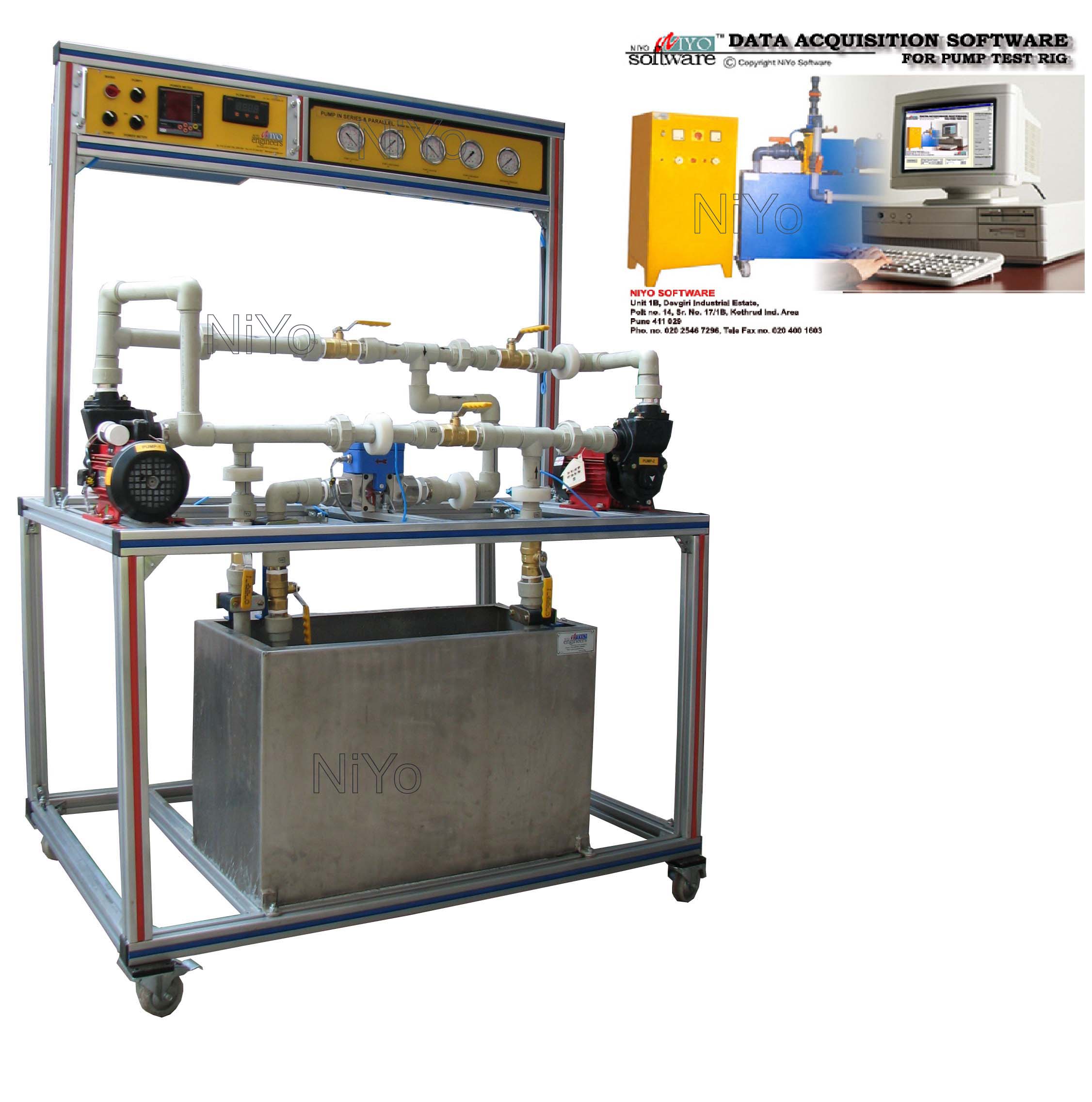
Computer Operated Water Pump Test Rig
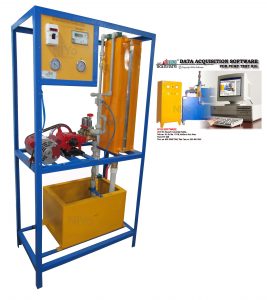
Description
NiYo Engineers’ Computer Operated Multiple Water Pump Test Rig is a training equipment that helps understand design and operation concepts of different types of water pumps.
This is a recirculating type pump test rig. Pump study is carried out by varying flow rates and pump speed. Transducers measure flow rate, suction and discharge pressure, power input to the pump and pump speed. These parameters are fed to the computer via a signal conditioning unit, the interfacing and communication system. The acquired data is analysed and displayed in tabular/ graphical format by a Windows based software. Facility to print the data helps student keep record of their experiments.
There is a facility to vary the speed of individual pump.
Different types of pumps can be studied on the same test rig. Sump tank, measuring instruments and piping is common to all the pumps. This saves space as well as gives good value for money.
Centrifugal pump, Reciprocating or any other type of water pump are supplied.
Components
- Centrifugal Pump
- Reciprocating Pump
- Electric Motor
- Flow transmitter
- Torque Transmitter
- Power transmitter
- Pressure Transmitter
- RPM Transmitter
- Sump tank
- Control Panel
- Data acquisition and interfacing system
- Software
- Computer
- Variable speed drive unit