PLC Training System with Elevator Control Application
Description
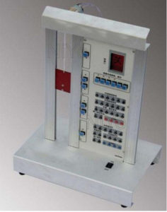
NiYo Engineers’ PLC Training System with Elevator Control application helps teach and familiarize students with real-life PLC application.
Operation and control of an Elevator is demonstrated. Various electro-mechanical components are controlled by a PLC. Controls of elevator like call the Car from landing, COP (Car operating Panel), Door Open-close, etc are demonstrated. This is four floor elevator model operated by a DC motor.
Components
- Model of Lift /Elevator
- DC Motor
- Pulley arrangement
- Elevator Car
- Elevator goors
- Switches
- Proximity Sensors
- Limit switches
- PLC with software
- Power supply